Chapter 6 - Light-Sensitive Navigation with

Phototransistors

Outcomes:

By the time you complete this section you will be able to:

  1. Understand what a phototransistor is and how it compares to an LED.
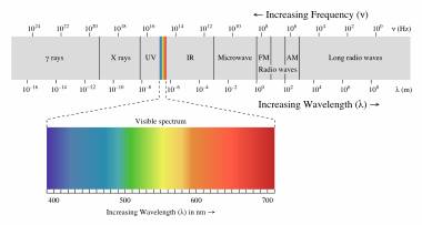
  2. Understand the concept of Illuminance and how it is used in science.
  3. Build a bright light detector circuit for the Boe-Bot
  4. Understand how the program receives input from the bright light detector circuit
  5. Build a charge transfer circuit for the Boe-Bot.
  6. Understand how the program receives input from the charge transfer circuit
  7. Program Boe-Bot so that it modifies its behavior when it detects bright light
  8. Program Boe-Bot to Measure light levels with phototransistors.
  9. Program Boe-Bot to use light to control its behavior while roaming
  10. Program Boe-Bot to create a graphic display of the light level detected.
  11. Demonstrate understanding of what a resistor is and how it is used in a circuit
  12. Know Ohms law and how it is used to calculate resistance, current, and voltage
  13. Explain how voltage is measured and apply it to Ohms law calculations
  14. Explain the concept of voltage decay and how it is measured.
  15. Explain what a transistor is and what it regulates.
  16. Explain what a capacitor is, how it is used in a circuit, and the unit of measure used for a capacitor.
  17. Demonstrate understanding of how to use the PWM command
  18. Demonstrate understanding of how to use the PULSOUT command
  19. Demonstrate understanding of what a constant declaration is and how it is used.
  20. Demonstrate understanding of MIN and MAX operators and how they are used.
  21. Demonstrate how to check how much RAM memory your program is using and how to modify the amount of memory used.
  22. Demonstrate how to modify a circuit to make it more or less sensitive to light.

Assignments:

  • View the videos in the video section of this lesson.
  • Read and follow the instructions in Robotics with the Boe-Bot  Chapter 6
  • Complete the Boe-Bot activities assigned by your instructor. If self-study, do all the “Your Turn” parts for each activity in the chapter.  Fill out the Observations section in this lesson for each Activity. (Note: It is only by typing in the commands that you truly begin to understand programming. So don’t short change yourself.)
  • Chapter 6 Vocabulary List - (PDF)
  • Review the Key Points or FAQs below.
  • Use the Observations again to Answer the questions at the end of the chapter.
  • Check your answers.
  • When complete, turn in the Observations Word Doc to your instructor (print, email or other method defined by your instructor). Self-study students can optionally send to a parent, mentor or friend.
Videos and Simulations

Chapter 6 Overview Video

Activity Videos:

Example Program Code

Activity #1 :

Activity #2 :

Activity #3 :

Activity #4 :

Key Points or FAQs:

How does a phototransistor work?

A phototransistor is a light–controlled current valve.  It lets more current through with brighter incident light and less current through with less bright light. 

What is a charge transfer circuit?

The charge transfer circuit consisted of a parallel capacitor and phototransistor connected to a pin with a resistor. In the circuit, the pin is used to charge the capacitor.  Then, it switched to input and the time it takes the capacitor’s voltage to decay as it lost its charge through the phototransistor is measured.  This decay time measurement turns out to be smaller with bright light and larger in shade.

What is voltage decay and how can it be used to measure light?

Voltage decay is the time it takes for a capacitor to drain down to a known amount.  RCTIME is used to measure the voltage decay.  It can be used to measure light in conjunction with a phototransistor.  Be measuring how long it takes for the capacitor to discharge, we can determine

What does the RCTIME command do?

The RCTIME command changes the Pin direction from output to input, and then waits for the I/O pin’s state to change, which happens when the voltage the circuit applies to the pin passes its 1.4 V logic threshold.  The RCTIME command stores the time measurement result in Variable.

What’s the difference between the PWM command and the PULSOUT command?

PWM stands for Pulse Wave Modulation.  The PWM command applies a rapid sequence of high/low signals to the I/O Pin for certain Duration in ms.  This PULSOUT command uses the same process as PWM, but the PWM signal is a more rapid sequence of pulses that’s especially useful for setting voltage across a capacitor through a resistor.

What is Ohms’s Law? Explain why it’s useful in electronics.

Ohm’s Law says that voltage across a resistor is equal to the current passing through it multiplied by its resistance.

For Example:

V = I × R

Voltage = Current x Resistance

This is useful in electronics so that unknown items can be calculated if any two items are known.  If you know the voltage and current, you can calculate resistance.

What is a capacitor? Why would you use one in electronics?

A capacitor is a device that stores electrical charge, and is used is many electric and electronic circuits.  Capacitors are like very small Batteries that can be charged and discharged very quickly.

What unit are Capacitors measured in?

Capacitors are measured in Farads.  Farads were originally developed for large electrical devices, but electronics uses very small capacitors, so many capacitors are measured in a millionth (microfarad) or a billionth (picofarad). For Example:

1 microfarad (μF) = one millionth (10-6) of a farad, or 1,000,000 pF, or 1,000 nF;

1 nanofarad (nF) = one billionth (10-9) of a farad, or 1,000 pF;

1 picofarad (pF) = one trillionth (10-12) of a farad.

What’s the difference between analog, digital and Binary in terms of the values returned?

Analog returns a range of values and can be several thousands of numbers which usually expresses a measurement.  Digital values are numbers expressed in digits.  Binary are digits that are expressed in either a zero or a one.

Why can’t we see infrared light?

Light is separated into a full spectrum of wavelengths (think about a rainbow).  Infrared light is outside of the wavelengths that the human eye can see.  The color spectrum below shows wavelengths that are within the range of the human eye. Notice that it just one small part of the whole wavelength.

photo